


IOT
An IoT Multi-Interface Gateway for Building a Smart Space
Time:2017-02-23 Click:8144
An IoT Multi-Interface Gateway for Building a Smart Space
1. Introduction
In recent years, Internet of Things (IoT) technology has attracted many attentions, making the unidentifiable objects into identifiable, recognized, interconnected intelligent objects. The development of IoT can support a variety of applications, including Intelligent Power Grid, Intelligent Transportation , Intelligent Medicine and Healthcare, Intelligent Art, Intelligent Logistics, Intelligent Environmental Monitoring, Smart Life, etc. However, their heterogeneous systems can only be utilized by using specific network packet conversion, which cannot be integrated with general heterogeneous network communication standards, such as Bluetooth, ZigBee, Infrared, etc. Therefore, the integration within the heterogeneous network is critical.
To solve the heterogeneous network transmission problems, this paper aims to design and implement a heterogeneous gateway which plays the role of translator of different wireless communication protocols. The designed heterogeneous gateway is able to communicate with a variety of smart objects using Wi-Fi, ZigBee, Bluetooth and IrDA standards. As a result, all objects can exchange information through the designed gateway.
The main contributions of this paper are itemized as follows.
1) The designed IoT gateway bridges the lower layer (perceive layer) and network layer of the IoT.
2) The designed IoT gateway enables the communication among different interfaces, including Wi-Fi, ZigBee, Bluetooth and 3G, which are general used by the smart objects in the IoT applications.
3) The gateway provides solution to the interference arisen from the coexistence of different protocols using the same ISM band.
The remaining part of this paper is organized as follows. Section 2 presents the system architecture of the designed IoT gateway. Sections 3 and 4 present the design of the hardware/Firmware components of the proposed gateway. Finally, the conclusions are drawn in Section 5.
2. System Architecture of an IoT Gateway
To integrate various devices with wireless communication protocols and communicate between heterogeneous networks, an Arduino microcontroller board, Octopus X wireless sensing module, ZX-Bluetooth chip module, WiFly GSX 802.11b/g wireless network chip module, and IR light-emitting diode (LED) transmitting module were employed to form a heterogeneous network gateway capable of supporting heterogeneous communications. Detailed descriptions of these hardware modules and their architectures are provided below.
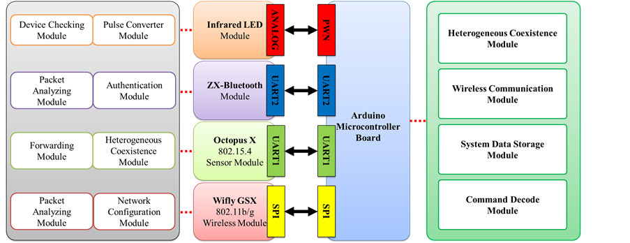
The logic architecture of a heterogeneous network gateway is shown in Figure 1. Both the Octopus X wireless sensing module and the ZX-Bluetooth chip module use the universal asynchronous receiver/transmitter (UART) communication interface to connect to the Arduino microcontroller board. The IR transmission module is connected to the pulse width modulation pins on the Arduino microcontroller board and simulates IR analog signals by using the digital pins.
3. Hardware Implementation and Integration
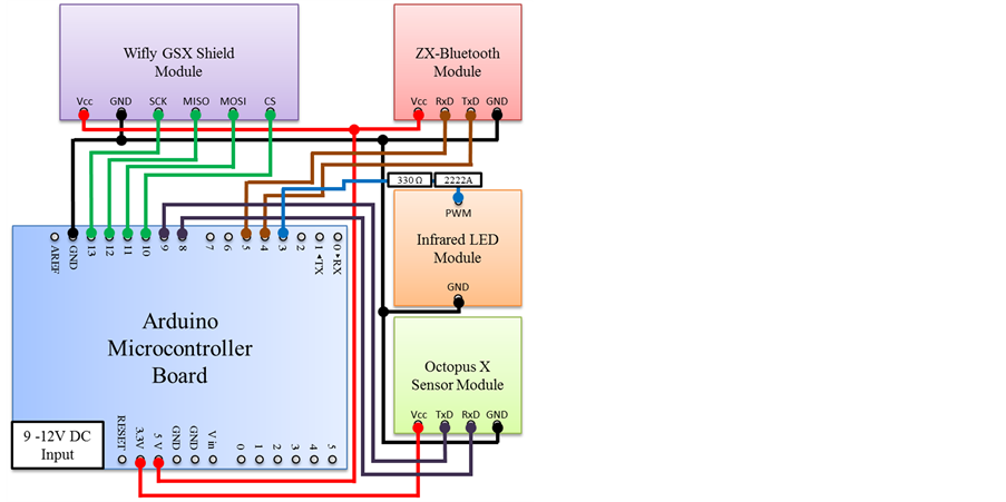
This section presents the hardware implementation of the heterogeneous network gateways. The integrated physical structure of the heterogeneous network gateway is shown in Figure 2.
The pins of each wireless communication module are connected to the pins of the Arduino microcontroller board. Figure 3 shows a circuit diagram of the heterogeneous network gateway. In this figure, the TxD and RxD pins of the ZX-Bluetooth chip module are connected to the fourth and fifth pins on the Arduino microcontroller board. By contrast, the TxD and RxD pins of the Octopus X wireless sensing module are connected to the eighth and ninth pins on the Arduino microcontroller board, respectively.
Figure 1.
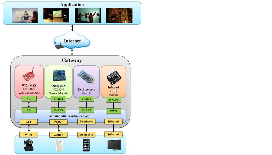
Figure 2.
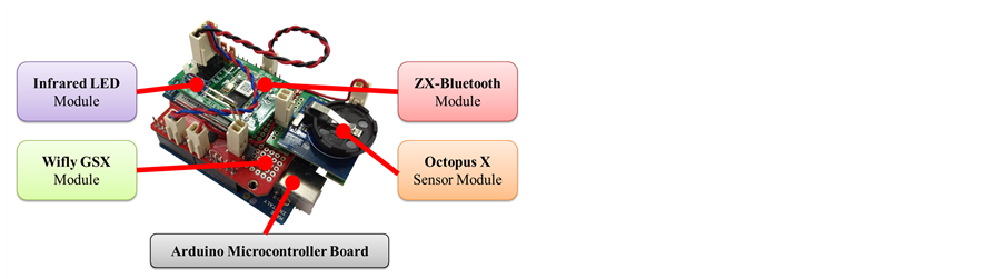
Figure 3.
4. Firmware Platform for Heterogeneous Network Gateway
The section presents the functions and corresponding firmware operations of the designed gateway. Figure 4 depicts the firmware modules of the heterogeneous network gateway.
The wireless communication module comprises the WiFly GSX, Octopus X, ZX-Bluetooth, and IR transfer modules.In the WiFly GSX wireless network chip module, the firmware functions comprise four modules, that is, the network configuration module, packet analyzing module, serial converter module, and transmission module. The function of the network configuration module is to configure the service set identifier (SSID) and frequency band of the wireless network to allow other embedded devices with wireless network functions to connect using the identification code. The function of the packet-analyzing module is to decrypt and analyze the data packets. The function of the serial converter module is to convert packets among different communication interfaces. The function of the transmission module is to transmit and receive data packets. Regarding the firmware system, embedded devices can be connected to the WiFly GSX module by using the SSID identification code configured through the network configuration module. When the connection of devices is complete, data packets are sent through the transmission module to the packet analyzing module for decryption and analysis. Then, using the serial converter module, analyzed data or control commands are sent to the Arduino microcontroller board for further processing.
Regarding the ZX-Bluetooth chip module, the firmware functions involve the following three modules: the authentication module, transmission module, and packet analyzing module. The authentication module aims to manage the connection between Bluetooth devices and perform device pairing and password authentication. The
Figure 4.
functions of the transmission module comprise the transmission and reception of external data and communication with the Arduino microcontroller board. The packet analyzing module is used to decrypt and analyze data packets. In the firmware system, when a pair of Bluetooth devices is connected, the authentication module is used for device pairing and password authentication. After authentication, data packets are received by the transmission module and transferred to the packet analyzing module to resolve data packets. Finally, the packets are returned to the transmission module and transferred to the Arduino microcontroller board through the UART communication interface.
In the Octopus X wireless sensing module, the firmware functions involve the following four modules: the node information module, identification module, debugging module, and forwarding module. The node information module exchanges module information using ZigBee protocols. The identification module is primarily responsible for providing embedded devices with a unique serial number that distinguishes every device. The debugging module is primarily employed for controlling the LED module on the Octopus X module to facilitate testing and debugging. The forwarding module is responsible for transferring collected data or commands to other devices through the UART communication interface between the Arduino microcontroller board and the Octopus X module. In the firmware system process, the Octopus X module collects current information from neighboring nodes by using the node information module to establish a star network. Then, the Octopus X module assigns a set of unique serial numbers to all embedded devices in the star network. When the Octopus X module receives a set of control commands from the Arduino microcontroller board, command packets are transmitted to the embedded device indicated in the network command through the forwarding module to control the device.
Regarding the IR transfer module, the firmware function involves three modules, namely, a pulse transmission module, pulse converter module, and device checking module. The pulse transmission module is responsible for receiving or sending IR pulse signals. The pulse converter module is used for converting the IR pulse and digital PWM signals. The device checking module resolves the IR code of each device and adjusts the transfer pulse formats according to the device codes. During the firmware system process, external IR signals can be received through the pulse transmission module and transformed into digital PWM signals resolvable in the Arduino microcontroller board by using the pulse converter module. After processing using the Arduino microcontroller board, signals are returned to the device checking module to adjust the pulse format of the devices. Finally, the IR pulse signals are then transmitted to the device through the pulse transmission module.
